Products+
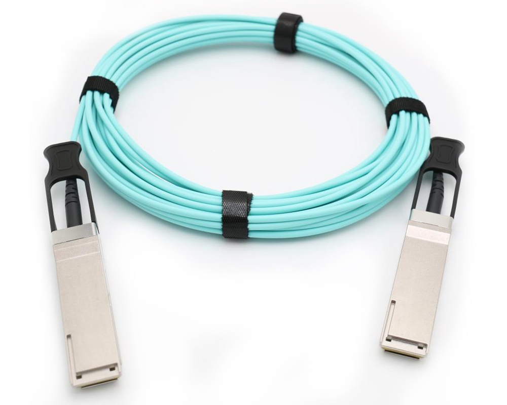
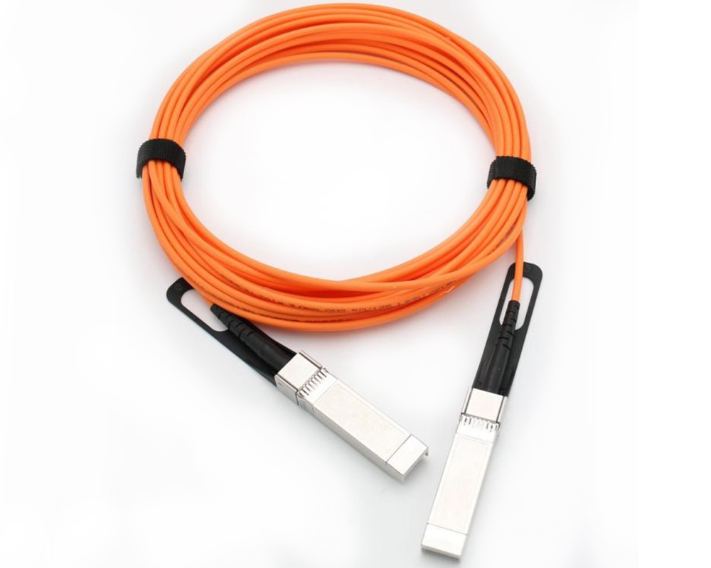
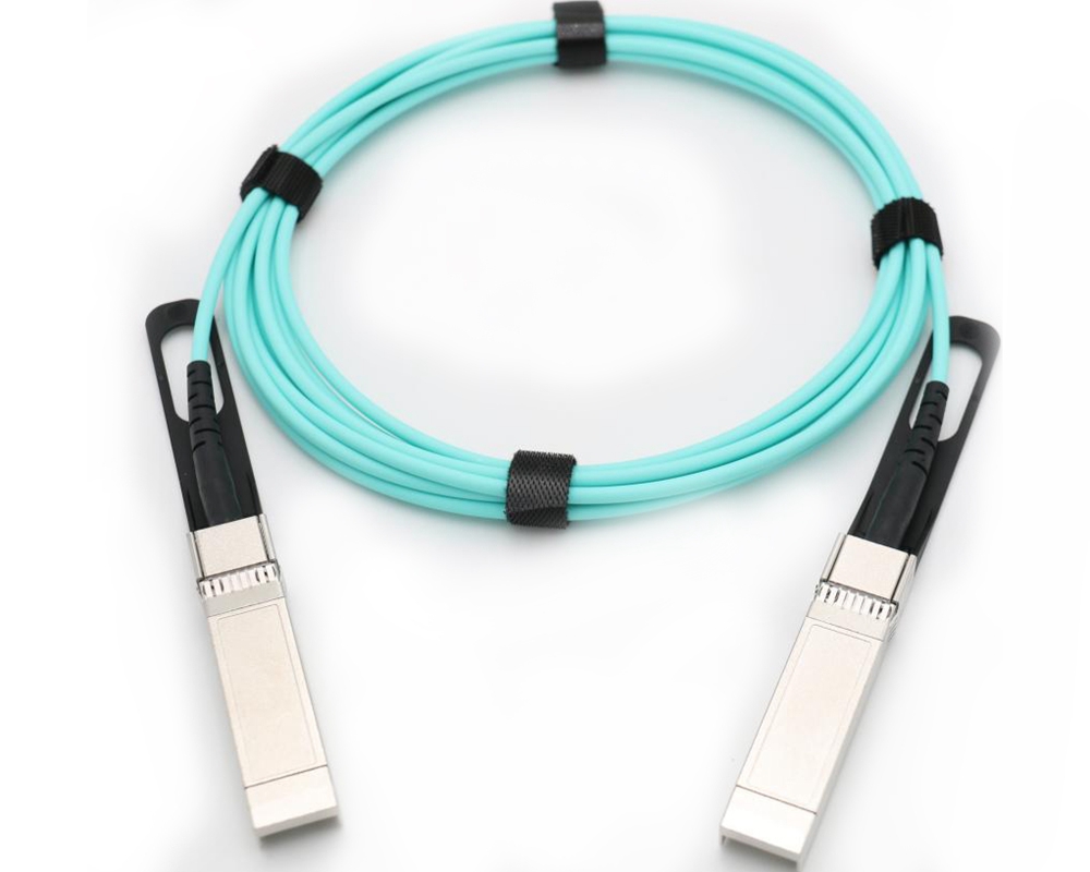
40G QSFP Compatible Active Optical Breakout Cable
40G QSFP Compatible Active Optical Breakout Cable, fully tested compatible for over 100 vendors.
1 Description :
40Gb/s QSFP+ AOC (Active Optical Cables) has four channels, each channel has a transmission rate of up to 10Gb/s, and the aggregate rate is up to 40Gb/s. Its low power consumption, low bit error rate, easy management, and high performance are widely used in medium and short-distance high-speed interconnection of network cards, switches, servers, supercomputers, and storage networks.
2 Features :
- 4 channels 850nm VCSEL and PIN
- Electrical interface compliant to SFF-8436
- Support 40GE data rate
- Hot Pluggable QSFP form factor
- Built-in digital diagnostic functions
- Operating case temperature 0°C to +70°C
- 3V power supply voltage
- Round OFNP-rated cable
3 Applications :
- 10Gbs~40Gbs Ethernet
- Data storage and communications industry
- Servers and data storage devices
- Switch/router/HBA, etc.
Outline drawing:
|
L |
L1 |
L2 |
L3 |
L4 |
W |
W1 |
W2 |
H |
H1 |
H2 |
H3 |
H4 |
H5 |
H6 |
|
|
Max |
72.2 |
- |
128 |
4.35 |
61.4 |
18.45 |
- |
6.2 |
8.6 |
12.4 |
5.35 |
2.5 |
1.6 |
2.0 |
- |
|
Type |
72.0 |
- |
- |
4.20 |
61.2 |
18.35 |
- |
- |
8.5 |
12.2 |
5.2 |
2.3 |
1.5 |
1.8 |
6.55 |
|
Min |
68.8 |
16.5 |
124 |
4.05 |
61.0 |
18.25 |
2.2 |
5.8 |
8.4 |
12.0 |
5.05 |
2.1 |
1.3 |
1.6 |
- |
|
L |
L1 |
L2 |
L3 |
L4 |
W |
W1 |
W2 |
H |
H1 |
H2 |
H3 |
H4 |
H5 |
H6 |
|
|
Max |
72.2 |
- |
128 |
4.35 |
61.4 |
18.45 |
- |
6.2 |
8.6 |
12.4 |
5.35 |
2.5 |
1.6 |
2.0 |
- |
|
Type |
72.0 |
- |
- |
4.20 |
61.2 |
18.35 |
- |
- |
8.5 |
12.2 |
5.2 |
2.3 |
1.5 |
1.8 |
6.55 |
|
Min |
68.8 |
16.5 |
124 |
4.05 |
61.0 |
18.25 |
2.2 |
5.8 |
8.4 |
12.0 |
5.05 |
2.1 |
1.3 |
1.6 |
- |
pinDescription
|
Pin |
Symbol |
Name/Description |
Notes |
|
1 |
GND |
Ground |
1 |
|
2 |
Tx2n |
Transmitter Inverted Data Input |
|
|
3 |
Tx2p |
Transmitter Non-Inverted Data Input |
|
|
4 |
GND |
Ground |
1 |
|
5 |
Tx4n |
Transmitter Inverted Data Input |
|
|
6 |
Tx4p |
Transmitter Non-Inverted Data Input |
|
|
7 |
GND |
Ground |
1 |
|
8 |
ModSelL |
Module Select |
|
|
9 |
ResetL |
Module Reset |
|
|
10 |
Vcc Rx |
+3.3V Power Supply Receiver |
|
|
11 |
SCL |
2-wire serial interface clock |
|
|
12 |
SDA |
2-wire serial interface data |
|
|
13 |
GND |
Ground |
1 |
|
14 |
Rx3p |
Receiver Non-Inverted Data Output |
|
|
15 |
Rx3n |
Receiver Inverted Data Output |
|
|
16 |
GND |
Ground |
1 |
|
17 |
Rx1p |
Receiver Non-Inverted Data Output |
|
|
18 |
Rx1n |
Receiver Inverted Data Output |
|
|
19 |
GND |
Ground |
1 |
|
20 |
GND |
Ground |
1 |
|
21 |
Rx2n |
Receiver Inverted Data Output |
|
|
22 |
Rx2p |
Receiver Non-Inverted Data Output |
|
|
23 |
GND |
Ground |
1 |
|
24 |
Rx4n |
Receiver Inverted Data Output |
|
|
25 |
Rx4p |
Receiver Non-Inverted Data Output |
|
|
26 |
GND |
Ground |
1 |
|
27 |
ModPrsL |
Module Present |
|
|
28 |
IntL |
Interrupt |
|
|
29 |
Vcc Tx |
+3.3V Power supply transmitter |
|
|
30 |
Vcc1 |
+3.3V Power supply |
|
|
31 |
LPMode |
Low Power Mode |
|
|
32 |
GND |
Ground |
1 |
|
33 |
Tx3p |
Transmitter Non-Inverted Data Input |
|
|
34 |
Tx3n |
Transmitter Inverted Data Input |
|
|
35 |
GND |
Ground |
1 |
|
36 |
Tx1p |
Transmitter Non-Inverted Data Input |
|
|
37 |
Tx1n |
Transmitter Inverted Data Input |
|
|
38 |
GND |
Ground |
1 |
Electrical Characteristics:
|
Parameter |
Symbol |
Min. |
Typ. |
Max. |
Units |
Notes |
|
|
ModSelL |
Module Select |
VOL |
0 |
- |
0.8 |
V |
|
|
Module Unselect |
VOH |
2.5 |
- |
VCC |
V |
|
|
|
LPMode |
Low Power Mode |
VIL |
0 |
- |
0.8 |
V |
|
|
Normal Operation |
VIH |
2.5 |
- |
VCC+0.3 |
V |
|
|
|
ResetL |
Reset |
VIL |
0 |
- |
0.8 |
V |
|
|
Normal Operation |
VIH |
2.5 |
- |
VCC+0.3 |
V |
|
|
|
ModPrsL |
Normal Operation |
VOL |
0 |
- |
0.4 |
V |
|
|
IntL |
Interrupt |
VOL |
0 |
- |
0.4 |
V |
|
|
Normal Operation |
VoH |
2.4 |
- |
VCC |
V |
|
|
|
Electrical transmitter Characteristics |
|||||||
|
Differential Date Input Swing |
Vout |
200 |
- |
1600 |
mV |
|
|
|
Output Differential Impedance |
ZD |
90 |
100 |
110 |
Ω |
|
|
|
Electrical Receiver Characteristics |
|||||||
|
Differential Data Output Swing |
Vin,P-P |
350 |
- |
800 |
mVPP |
|
|
|
Bit Error Rate |
BER |
|
|
E-12 |
|
1 |
|
|
Input Differential Impedance |
ZIN |
90 |
100 |
110 |
Ω |
|
|
RecommendedOperating Conditions:
|
Parameter |
Symbol |
Min. |
Typical |
Max. |
Unit |
Notes |
|
Operating Case Temperature |
TC |
0 |
- |
+70 |
°C |
|
|
Power Supply Voltage |
Vcc |
3.14 |
3.3 |
3.47 |
V |
|
|
Power Dissipation |
Pd |
- |
- |
1.5 |
W |
1 |
|
Bit Rate |
BR |
1.25 |
10.3125 |
- |
Gbps |
|
AbsoluteMaximum Ratings :
|
Parameter |
Symbol |
Min. |
Typical |
Max. |
Unit |
Notes |
|
Supply Voltage |
Vcc3 |
-0.5 |
- |
+3.6 |
V |
|
|
Storage Temperature |
Ts |
-10 |
- |
+70 |
°C |
|
|
Operating Humidity |
RH |
+5 |
- |
+85 |
% |
1 |