Products+
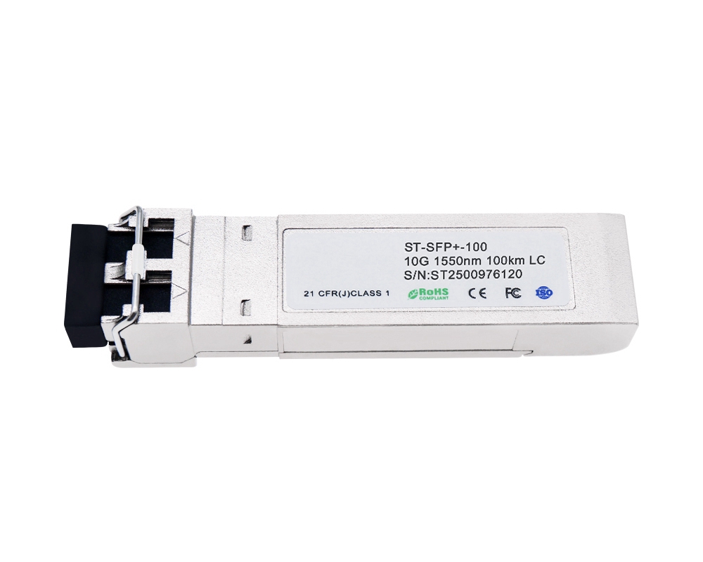
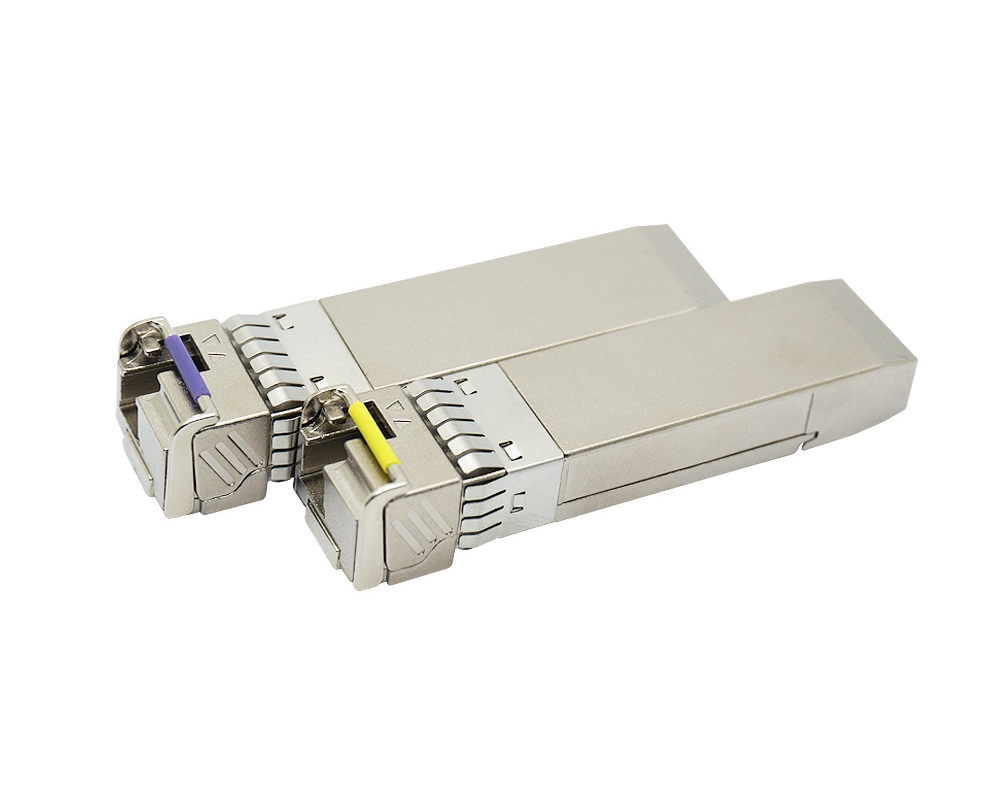
10G SFP+ 1550nm 100km Compatible Transceiver
10G 1550nm 100km SFP+ Transceiver, link length up to 100km ,fully tested compatible for over 100 vendors.
Features
- Compliant with SFF-8431 and IEE802.3ae
- Data rate selectable ≤4.25Gbps or 9.95Gbps to 11.3Gbps bit rates
- Cooled EML transmitter and APD receiver
- 5. Low Power Dissipation 1.4W Typical (Maximum:2W)
- -5ºC to 70ºC Operating Case Temperature
- Single 3.3V power supply
- Diagnostic Performance Monitoring of module temperature, supply Voltages, laser bias current, transmit optical power, receive optical power
- RoHS compliant and lead free
Applications
- 10G Ethernet
- 10G Fiber Channel (with/without FEC)
Description
The SFP+ Transceiver is designed for 8.5G/10G Fiber- Channel and 10GBE applications. The transceiver consists of two sections: The transmitter section incorporates a colded EML laser. And the receiver section consists of a APD photodiode integrated with a TIA. All modules satisfy class I laser safety requirements.SFP+ Digital diagnostics functions are available via a 2-wire serial interface, as specified in SFF-8472, which allows real-time access to device operating parameters such as transceiver temperature, laser bias current, transmitted optical power, received optical power and transceiver supply voltage.
Absolute Maximum Ratings
|
Parameter |
Symbol |
Min |
Max |
Unit |
|
Supply Voltage |
Vcc |
-0.5 |
3.8 |
V |
|
Storage Temperature |
Tst |
-40 |
85 |
ºC |
|
Relative Humidity |
Rh |
0 |
85 |
% |
Operating Conditions
|
Parameter |
Symbol |
Min |
Typical |
Max |
Unit |
|
Supply Voltage |
Vcc |
3.13 |
3.3 |
3.47 |
V |
|
Supply current [1] |
Icc |
|
420 |
610 |
mA |
|
Operating Case temperature |
Tca |
-5 |
- |
70 |
ºC |
|
Module Power Dissipation [2] |
Pm |
- |
1.4 |
2 |
W |
Notes:
[1] Supply current is shared between VCCTX and VCCRX. Typical Supply current test at 25℃,Max Supply current test at 60~70℃
[2] In-rush is defined as current level above steady state current requirements
Transmitter Specifications – Optical
|
Parameter |
Symbol |
Min |
Typical |
Max |
Unit |
|
Center Wavelength |
lc |
1528 |
|
1565 |
nm |
|
Optical Average Power |
Po |
0 |
- |
+4 |
dBm |
|
Side Mode Suppression Ratio |
SMSR |
30 |
- |
- |
dB |
|
Optical Transmit Power (disabled) |
PTX_DISABLE |
- |
- |
-30 |
dBm |
|
Extinction Ratio |
ER |
9 |
|
- |
dB |
|
RIN21OMA |
|
|
|
-128 |
dB/Hz |
|
Optical Return Loss Tolerance |
|
|
|
21 |
dB |
|
Dispersion penalty(1600ps/nm) |
DP |
|
|
2 |
dB |
Transmitter Specifications – Electrical
|
Parameter |
Symbol |
Min |
Typical |
Max |
Unit |
|
Data Rate |
Mra |
- |
10.3 |
11.3 |
Gbps |
|
Input differential impedance |
Rim |
- |
100 |
- |
Ω |
|
Differential data Input |
VtxDIFF |
120 |
- |
850 |
mV |
|
Transmit Disable Voltage |
VD |
2.0 |
- |
Vcc3+0.3 |
V |
|
Transmit Enable Voltage |
Ven |
0 |
- |
+0.8 |
V |
|
Transmit Disable Assert Time |
Vn |
- |
- |
100 |
us |
Receiver Specifications – Optical
|
Parameter |
Symbol |
Min |
Typical |
Max |
Unit |
|
Input Operating Wavelength |
λ |
1110 |
- |
1650 |
nm |
|
Receiver sensitivity [1] |
|
- |
- |
-24 |
dBm |
|
Maximum Input Power |
RX-overload |
- |
- |
-8 |
dBm |
|
Loss of Signal Asserted |
|
-34 |
- |
- |
dBm |
|
LOS De-Asserted |
|
- |
- |
-24 |
dBm |
|
LOS Hysteresis |
|
0.5 |
- |
- |
dB |
Notes:
[1] Measured with conformance test signal for BER = 10–12. PRBS31, Data Rate=10.3Gbps.
Receiver Specifications – Electrical
|
Parameter |
Symbol |
Min |
Typical |
Max |
Unit |
|
Data Rate |
Mra |
- |
10.3 |
11.3 |
Gbps |
|
Differential Output Swing |
Vout P-P |
350 |
- |
850 |
mV |
|
Rise/Fall Time |
Tr / Tf |
24 |
- |
- |
ps |
|
Loss of Signal –Asserted |
VOH |
2 |
- |
Vcc3+0.3- |
V |
|
Loss of Signal –Negated |
VOL |
0 |
- |
+0.4 |
V |
Figure1.Electrical Pin-out Details
Pin Descriptions
|
Pin |
Symbol |
Name/Description |
|
1 |
VEET [1] |
Transmitter Ground |
|
2 |
Tx_FAULT [2] |
Transmitter Fault |
|
3 |
Tx_DIS [3] |
Transmitter Disable. Laser output disabled on high or open |
|
4 |
SDA [2] |
2-wire Serial Interface Data Line |
|
5 |
SCL [2] |
2-wire Serial Interface Clock Line |
|
6 |
MOD_ABS [4] |
Module Absent. Grounded within the module |
|
7 |
RS0 [5] |
RS0 for Rate Select: Open or Low = Module supports ≤4.25Gbps High = Module supports 9.95 Gb/s to 10.3125 Gb/s |
|
8 |
RX_LOS [2] |
Loss of Signal indication. Logic 0 indicates normal operation |
|
9 |
RS1 [5] |
No connection required |
|
10 |
VEER [1] |
Receiver Ground |
|
11 |
VEER [1] |
Receiver Ground |
|
12 |
RD- |
Receiver Inverted DATA out. AC Coupled |
|
13 |
RD+ |
Receiver DATA out. AC Coupled |
|
14 |
VEER [1] |
Receiver Ground |
|
15 |
VCCR |
Receiver Power Supply |
|
16 |
VCCT |
Transmitter Power Supply |
|
17 |
VEET [1] |
Transmitter Ground |
|
18 |
TD+ |
Transmitter DATA in. AC Coupled |
|
19 |
TD- |
Transmitter Inverted DATA in. AC Coupled |
|
20 |
VEET [1] |
Transmitter Ground |
Notes:
[1] Module circuit ground is isolated from module chassis ground within the module.
[2].should be pulled up with 4.7k – 10k ohms on host board to a voltage between 3.15Vand 3.6V.
[3]Tx_Disable is an input contact with a 4.7 kΩ to 10 kΩ pullup to VccT inside the module.
[4]Mod_ABS is connected to VeeT or VeeR in the SFP+ module. The host may pull this contact up to Vcc_Host with a resistor in the range 4.7 kΩ to10 kΩ.Mod_ABS is asserted “High” when the SFP+ module is physically absent from a host slot.
[5] RS0 and RS1 are module inputs and are pulled low to VeeT with > 30 kΩ resistors in the module.
Figure2. Host Board Power Supply Filters Circuit
Figure3. Host-Module Interface
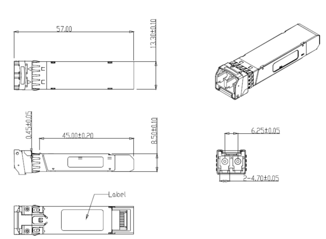
Figure4. Mechanical Specifications
Ordering information
|
Part Number |
Description |
|
ST-SFP+-100 |
10Gbps 1550nm 100km LC SFP+ Transceiver 0ºC ~ +70ºC |