Products+
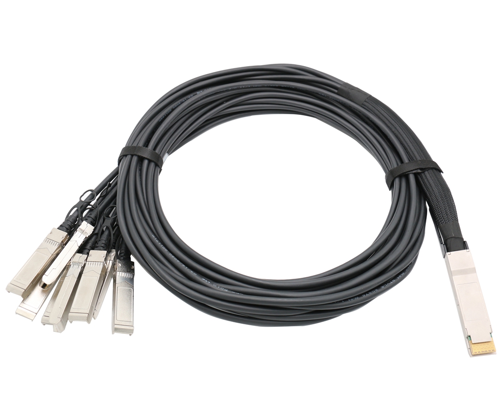
100Gbps QSFP28 To 4x 25G SFP28 Compatible Direct Attach Copper Twinax Passive Cable
100Gbps QSFP28 To 4x 25G SFP28 Compatible Direct Attach Copper Twinax Passive Cable, fully tested compatible for over 100 vendors.
Compatible Device: Cisco QSFP-100G-CU1M, Cisco QSFP-100G-CU2M, Cisco QSFP-100G-CU3M, Cisco QSFP28-100G-CU1M, Cisco QSFP28-100G-CU3M
Description :
100G QSFP28 is based on a 4X25G or 4X28G structure, meeting the needs of next-generation 100G switches, servers, routers and other product applications. The QSFP28 cable assembly uses an optimized design to reduce crosstalk and insertion loss, has excellent signal integrity, and fully complies with the next-generation 100G Ethernet and InfiniBand EDR standards.
SFP28 is based on SFP+ equivalent form factor, supports 25G Ethernet standard, can provide 25Gb/s error-free transmission, and is used in high-density 25G Ethernet switches and network interfaces. 100G QSFP28 To 4x25G SFP28 supports two interface device interconnection, single channel The transmission rate is 25Gbps.
Features
- Enhanced EMI / EMC performance
- Compliant with the IEEE 802.3bj Infiniband EDR specifications
- Meets SFF-8636、SFF-8402
- Support serial ID function through EEPROM
- 30AWG to 26AWG cable available
- RoHS
Applications :
10G/25G/40G /100g Ethernet
Infiniband SDR, DDR, QDR, FDR, EDR
Switches, routers, data centers, cloud servers
Electrical Performance:
-
(Signal Integrity)
|
(ITEM) |
(REQUIREMENT) |
(TEST CONDITION) |
|
|
|
Cable |
105+5/-10Ω |
|
|
|
Impedance |
|
|
|
(Differe |
Paddle Card |
100±10Ω |
Rise time of 25ps |
|
ntial |
Impedance |
(20 % - 80 %). |
|
|
Impedan |
Cable |
|
|
|
ce) |
Termination |
100±15Ω |
|
|
|
Impedance |
|
|
|
|
Return_loss(f)≥ 16.5-2√f 0.05≤f﹤4.1 10.66-14log10(f/ 5.5) 4.1≤f≤19 Where f is the frequency in GHz Return loss(f) is the return loss at frequency f |
|
|
|
[Differential (Input/Output)Return |
10MHz≤f ≤19GHz |
||
|
loss SDD11/SDD22] |
|
||
|
[Differential to common-mode (Input/Output)Return loss SCD11/SCD22] |
Return_loss(f)≥ 22-(20/25.78)f 0.01≤f﹤12.89 15-(6/25.78)f 12.89≤f≤19 Where f is the frequency in GHz Return_loss(f) is the Differential to common-mode return loss at frequency f |
10MHz≤f ≤19GHz |
|
|
[Common-mode to Common-mode (Input/Output)Return loss SCC11/SCC22] |
Return_loss(f)≥2dB 0.2≤f≤19 Where f is the frequency in GHz Return_loss(f) is the common-mode to common-mode return loss at frequency f |
10MHz≤f ≤19GHz |
||||||
|
[Differential Insertion Loss (SDD21 Max.)] |
(Differential InsertionLoss Max. For TPa to TPb Excluding Test fixture ) |
10MHz≤f ≤19GHz |
||||||
|
F AWG |
1.25GHz |
2.5GHz |
5.0GHz |
7.0GHz |
10Ghz |
12.89Ghz |
||
|
30(1m) Max. |
4.5dB |
5.4dB |
6.3dB |
7.5dB |
8.5dB |
10.5dB |
||
|
30/28( 3m)Ma x. |
7.5dB |
9.5dB |
12.2dB |
14.8dB |
18.0dB |
21.5dB |
||
|
26(3m) Max. |
5.7dB |
7.2dB |
9.9 dB |
11.9dB |
14.1dB |
16.5dB |
||
|
26/25( 5m)Ma x. |
7.8dB |
10.0dB |
13.5dB |
16.0dB |
19.0dB |
22.0dB |
||
|
|
||||||||
|
Differential to common-mode Conversion Loss-Differential Insertion Loss(SCD21-SDD21) |
10 0.01≤f﹤12.89 Conversion _loss(f) – IL(f)≥ 27-(29/22)f 12.89 ≤ f ﹤
Where f is the frequency in GHz Conversion_loss(f ) is the cable assembly differential to common-mode conversion loss IL(f) is the cable assembly insertion loss |
10MHz≤f ≤19GHz |
||||||
|
[MDNEXT(multiple disturber near-end crosstalk)] |
≥26dB @12.89GHz |
10MHz≤f ≤19GHz |
||||||
-
(Other Electrical Performance)
|
(ITEM) |
(REQUIREMENT) |
(TEST CONDITON) |
|
[Low Level Contact Resistance] |
70milliohms Max. From initial. |
EIA-364-23:Apply a maximum voltage of 20mV And a current of 100 mA. |
|
Insulation Resistance |
10Mohm(Min.) |
EIA364-21:AC 300V 1minute |
|
[Dielectric Withstanding Voltage] |
NO disruptive discharge. |
EIA-364-20:Apply a voltage of 300 VDC for 1minute between adjacent terminals And between adjacent terminals and ground. |
Environment Performance
|
(ITEM) |
(REQUIREMENT) |
(TEST CONDITON) |
|
[Operating Temp. Range] |
-20°C to +75°C |
Cable operating temperature range. |
|
Storage Temp. Range (in packed condition)] |
-40°C to +80°C |
Cable storage temperature range in packed condition. |
|
[Thermal Cycling Non-Powered] |
No evidence of physical damage |
EIA-364-32D, Method A, -25 to 90C, 100 cycles, 15 min. dwells |
|
[Salt Spraying] |
48 hours salt spraying after shell corrosive area less than 5%. |
EIA-364-26 |
|
Mixed Flowing Gas |
Pass electrical tests per 3.1 after stressing. (For connector only) |
EIA-364-35 Class II,14 days. |
|
Temp. Life |
No evidence of physical damage |
EIA-364-17C w/ RH, Damp heat 90℃ at 85% RH for 500 hours then return to ambient |
|
Cable Cold Bend |
4H,No evidence of physical damage |
Condition: -20℃±2℃, mandrel diameter is 6 times the cable diameter. |
Mechanical and Physical Characteristics
|
(ITEM) |
(REQUIREMENT) |
(TEST CONDITON) |
|
Vibration |
Pass electrical tests per 3.1 after stressing. |
Clamp & vibrate per EIA-364-28E, TC-VII, test condition letter – D, 15 minutes in X, Y & Z axis. |
|
Twist |
No evidence of physical damage |
Twist cable 180° (±90° from nominal position) for 100 cycles at 30 cycles per minute with a 0.5kg load applied to the cable jacket. Clamp position: 300mm |
|
Cable Flex |
No evidence of physical damage |
Flex cable 180° for 20 cycles (±90° from nominal position) at 12 cycles per minute with a 1.0kg load applied to the cable jacket. Flex in the boot area 90º in each direction from vertical. Per EIA-364-41C |
|
Cable Plug Retention in Cage |
90N Min. No evidence of physical damage |
Force to be applied axially with no damage to cage. Per SFF 8661 Rev 2.1 Pull on cable jacket approximately 1 ft behind cable plug. No functional damage to cable plug below 90N. Per SFF-8432 Rev 5.0 |
|
Cable Retention in Plug |
90N Min. No evidence of physical damage |
Cable plug is fixtured with the bulk cable hanging vertically. A 90N axial load is applied (gradually) to the cable jacket and held for 1 minute. Per EIA-364-38B |
|
Mechanical Shock |
Pass electrical tests Per 3.1 after stressing. |
Clamp and shock per EIA-364-27B, TC-G,3 times in 6 directions, 100g, 6ms. |
|
Cable Plug Insertion |
40N Max.(QSFP28) 18N Max.(SFP28) |
Per SFF8661 Rev 2.1 Per SFF-8432 Rev 5.0 |
|
Cable plug Extraction |
30N Max. (QSFP28) 12.5N Max. (SFP28) |
Place axial load on de-latch to de-latch plug.Per SFF8661 Rev 2.1 Measure without the aid of any cage kick-out springs. Place axial load on de-latch to de-latch plug. Per SFF-8432 Rev 5.0 |
|
Durability |
50 cycles,No evidence of physical damage |
EIA-364-09, perform plug &unplug cycles:Plug and receptacle mate rate: 250times/hour. 50times for QSFP28/SFP28 module (CONNECTOR TO PCB) |