Back view of the system of Dell EMC PowerEdge R740xd
2023-08-11
In order to enhance customers' understanding of Dell PowerEdge R740xd, we have published a series of articles, in this article, we will introduce the configuration validation of Dell PowerEdge R740xd to you in the form of tables.
Figure 1. Back view of 4 x 2.5 inch drive system
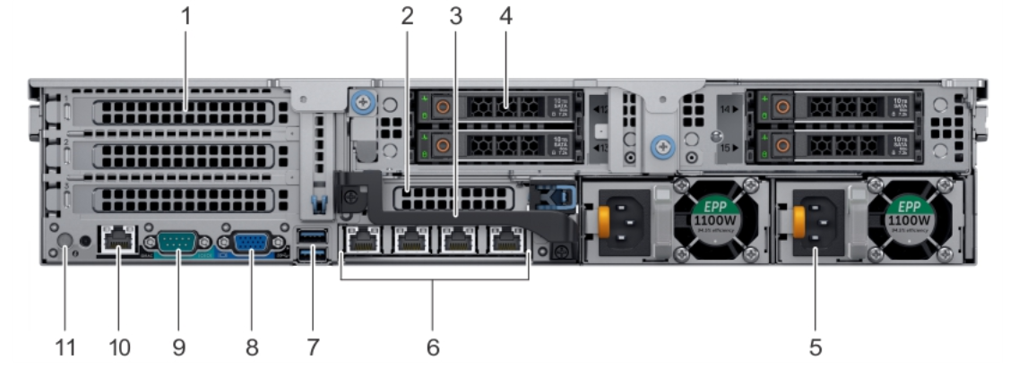
Table 1. Features available on the back view of 4 x 2.5 inch drive system
| ITEM | PANELS, PORTS AND SLOTS | ICON | DESCRIPTION |
| 1 | Full-height PCIe expansion card slot (3) | N/A | The PCIe expansion card slot (riser 1) connects up to three full-height PCIe expansion cards to the system. |
| 2 | Half-height PCIe expansion card slot | N/A | The PCIe expansion card slot (riser 2) connects one half-height PCIe expansion cards to the system. |
| 3 | Rear handle | N/A | The rear handle can be removed to enable any external cabling of PCIe cards that are installed in the PCIe expansion card slot 6. |
| 4 | Drive slots | N/A | Enable you to install drives that are supportedon your system. |
| 5 | Power supply unit (2) | N/A | The rear handle can be removed to enable any external cabling of PCIe cards that are installed in the PCIe expansion card slot 6. |
| 6 | NIC ports |  |
TheNIC ports that are integrated on the network daughter card (NDC) providenetwork connectivity. |
| 7 | USB port (2) | The USB ports are 9-pin and 3.0-compliant. These ports enable you to connect USB devices to the system. |
|
| 8 | VGA port |  |
Enables you to connect a display deviceto the system. |
| 9 | Serial port | Enables you to connect a serial deviceto the system. |
| 10 | iDRAC9 dedicated port | Enables you to remotely access iDRAC. | |
| 11 | System identification button |  |
The System Identification (ID) button is available on the front and back of the systems. Press the button to identify a system in a rack by turning on the system ID button. You can also use the system ID button to reset iDRAC and to access BIOS using the step through mode. |
Figure 2. Back view of 2 x 3.5 inch drive system
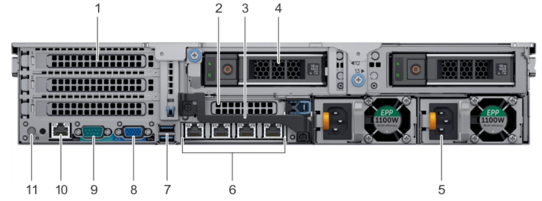
Table 2. Features available on the back view of 2 x 3.5 inch drive system
| ITEM | PANELS, PORTS AND SLOTS | ICON | DESCRIPTION |
|---|---|---|---|
| 1 | Full-height PCIe expansion card slot (3) | N/A | The PCIe expansion card slot (riser 1) connects up to three full-height PCIe expansion cards to the system. |
| 2 | Half-height PCIe expansion card slot | N/A | The PCIe expansion card slot (riser 2) connects one half-height PCIe expansion cards to the system. |
| 3 | Rear handle | N/A | The rear handle can be removed to enable any external cabling of PCIe cards that are installed in the PCIe expansion card slot 6. |
| 4 | Drive slots | N/A | Enable you to install drives that are supportedon your system. |
| 5 | Power supply unit (2) | N/A | The rear handle can be removed to enable any external cabling of PCIe cards that are installed in the PCIe expansion card slot 6. |
| 6 | NIC ports | |
TheNIC ports that are integrated on the network daughter card (NDC) providenetwork connectivity. |
| 7 | USB port (2) | The USB ports are 9-pin and 3.0-compliant. These ports enable you to connect USB devices to the system. | |
| 8 | VGA port | |
Enables you to connect a display deviceto the system. |
| 9 | Serial port | Enables you to connect a serial deviceto the system. |
| 10 | iDRAC9 dedicated port |  |
Enables you to remotely access iDRAC. |
| 11 | System identification button | |
The System Identification (ID) button is available on the front and back of the systems. Press the button to identify a system in a rack by turning on the system ID button. You can also use the system ID button to reset iDRAC and to access BIOS using the step through mode. |