Products+
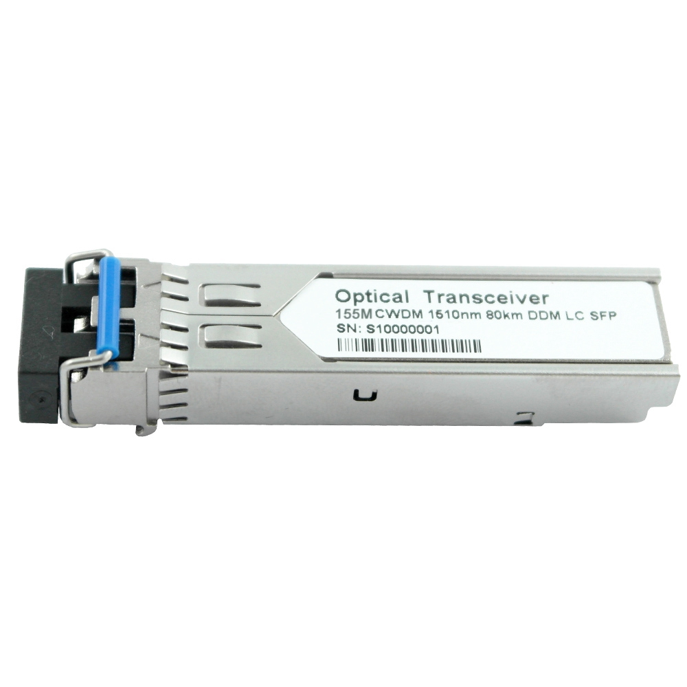
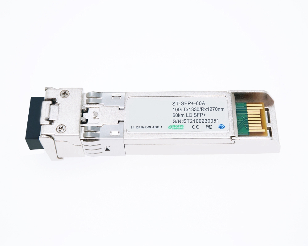
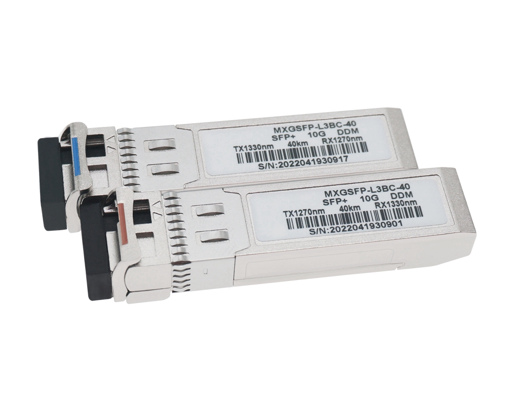
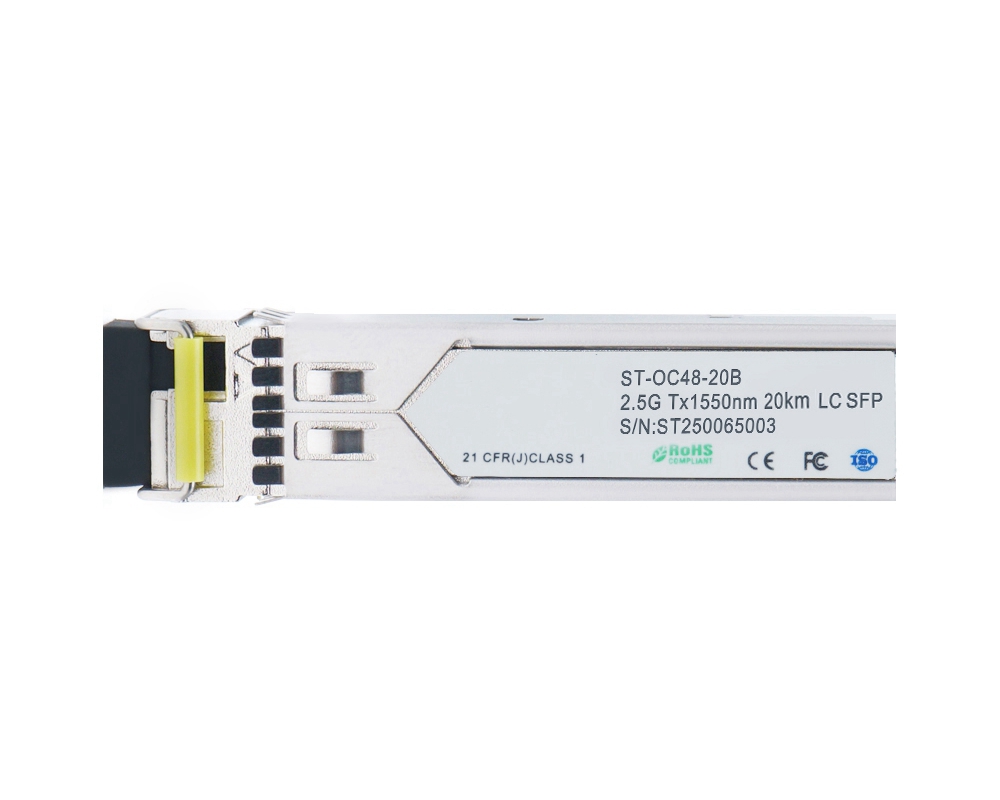
1.25Gbps Tx1310/Rx1490nm 20km Compatible SFP Bi-Directional Transceiver
1.25Gbps SFP Bi-Directional Transceiver, 20KM Reach, LC Connector SMF Tx1310nm/Rx1490nm, fully tested compatible for over 100 vendors.
Features
- Single Mode bi-directional Transmission
- SFP Multi-source Package with LC Receptacle
- Up to 1.25Gb/s Data Links
- Hot-Pluggable Capability
- Up to 20 km on 9/125μm SMF
- Single +3.3V Power Supply
- Built-in WDM
- Isolation > 30dB, Cross Talk < -45dB
- Monitoring Interface Compliant with SFF-8472
- Metal Enclosure, Excellent EMI & ESD Protection
- Compliant with Specifications for IEEE802.3Z
- Compliant with Bellcore TA-NWT-000983
- Eye Safety Designed to Meet Laser Class1, Compliant with IEC60825-1
- RoHS Compliant
Applications
- Gigabit Ethernet
- Fiber Channel
- WDM Application
Description
The Bi-Directional transceiver is a high performance, cost effective module ,which is compliant with LC Optics interface with built in WDM for Bi-Directional serial optical data communication applications. This module is designed for Single-Mode single fiber, operates at the normal wavelength of 1310/1490nm.
Standard AC coupled CML for high speed signal and LVTTL control and monitor signals.
The transmitter section incorporates FP and driver IC with temperature compensation and automatic power control circuit, which make the transmitter section output power and Extinction ration stabled in operation temperature.
The receiver section incorporates an efficient InGaAs photodiode and transimpedance with AGC for wide dynamic range.
-
Absolute Maximum Ratings
|
Parameter |
Symbol |
Min. |
Typical |
Max. |
Unit |
|
|
Storage Temperature |
TS |
-40 |
|
+85 |
°C |
|
|
Supply Voltage |
VCCT, R |
-0.5 |
|
4 |
V |
|
|
Relative Humidity |
RH |
0 |
|
85 |
% |
|
|
Case Operating Temperature |
Industrial |
Top |
-40 |
|
85 |
C |
|
Extended |
-5 |
|
85 |
|||
|
Commercial |
0 |
|
70 |
|||
-
Recommended Operating Environment:
|
Parameter |
Symbol |
Min. |
Typical |
Max. |
Unit |
|
|
Case operating Temperature |
Industrial |
TC |
|
|
|
|
|
Extended |
|
|
|
|
||
|
Commercial |
0 |
|
+70 |
°C |
||
|
Supply Voltage |
VCCT, R |
3.0 |
|
3.6 |
V |
|
|
Power Supply Rejection |
|
100 |
|
|
mVP-P |
|
-
Electrical Characteristics(TOP = 0 to 70 °C, VCC = 3.0 to 3.60 Volts)
|
Parameter |
Symbol |
Min. |
Typical |
Max. |
Unit |
Note |
|
Supply Voltage |
Vcc |
3.0 |
3.30 |
3.60 |
V |
|
|
Supply Current |
Icc |
|
160 |
280 |
mA |
|
|
Inrush Current |
Isurge |
|
|
Icc+30 |
mA |
|
|
Maximum Power |
Pmax |
|
|
1.0 |
W |
|
|
Transmitter Section: |
|
|||||
|
Input differential impedance |
Rin |
90 |
100 |
110 |
|
|
|
Single ended data input swing |
Vin PP |
200 |
|
1200 |
mVp-p |
|
|
Transmit Disable Voltage |
VD |
Vcc – 1.3 |
|
Vcc |
V |
2 |
|
Transmit Enable Voltage |
VEN |
Vee |
|
Vee+ 0.8 |
V |
|
|
Transmit Disable Assert Time |
Tdessert |
|
|
10 |
us |
|
|
Receiver Section: |
|
|||||
|
Single ended data output swing |
Vout,pp |
300 |
|
1000 |
mv |
3 |
|
Data output rise time |
tr |
|
|
150 |
ps |
4 |
|
Data output fall time |
tf |
|
|
150 |
ps |
4 |
|
LOS Fault |
Vlosfault |
Vcc – 0.5 |
|
VCC_host |
V |
5 |
|
LOS Normal |
Vlos norm |
Vee |
|
Vee+0.5 |
V |
5 |
|
Power Supply Rejection |
PSR |
100 |
|
|
mVpp |
6 |
|
Deterministic Jitter Contribution |
RXΔDJ |
|
|
51.7 |
ps |
7 |
|
Total Jitter Contribution |
RXΔTJ |
|
|
122.4 |
ps |
|
Note:
- AC coupled.
- Or open circuit.
- Into 100 ohm differential termination.
- 20 – 80 %
- LOS is LVTTL. Logic 0 indicates normal operation; logic 1 indicates no signal detected.
- All transceiver specifications are compliant with a power supply sinusoidal modulation of 20 Hz to 1.5MHz up to specified value applied through the power supply filtering network shown on page 23 of the Small Form-factor Pluggable (SFP) Transceiver Multi-Source Agreement (MSA), September 14, 2000.
- Measured with DJ-free data input signal. In actual application, output DJ will be the sum of input DJ and . DJ.
-
Optical Parameters(TOP = 0 to 70 °C, VCC = 3.0 to 3.60 Volts)
|
Parameter |
Symbol |
Min. |
Typical |
Max. |
Unit |
Note |
|
Transmitter Section: |
||||||
|
Center Wavelength |
λc |
1270 |
1310 |
1360 |
nm |
1 |
|
Spectral Width |
σ |
|
|
3 |
nm |
|
|
Optical Output Power |
Pout |
-9 |
|
-3 |
dBm |
2 |
|
Optical Rise/Fall Time |
tr / tf |
|
|
160 |
ps |
3 |
|
Extinction Ratio |
ER |
9 |
|
|
dB |
|
|
Deterministic Jitter Contribution |
TXΔDJ |
|
|
56.5 |
ps |
4 |
|
Total Jitter Contribution |
TXΔTJ |
|
|
119 |
ps |
|
|
Eye Mask for Optical Output |
Compliant with Eye Mask Defined in IEEE 802.3 standard |
|
||||
|
Relative Intensity Noise |
RIN |
|
|
-120 |
dB/Hz |
|
|
Receiver Section: |
|
|||||
|
Optical Input Wavelength |
|
1480 |
1490 |
1500 |
nm |
|
|
Optical Input Power |
Pin |
-23 |
|
-3 |
dBm |
5.6 |
|
Receiver Reflectance |
|
12 |
|
|
dB |
|
|
Receiver Overload |
Pol |
|
|
-3 |
dBm |
5.6 |
|
RX Sensitivity |
Sen |
|
|
-23 |
dBm |
5.6 |
|
RX_LOS Assert |
LOS A |
-34 |
|
|
dBm |
|
|
RX_LOS Deassert |
LOS D |
|
|
-24 |
dBm |
|
|
RX_LOS Hysteresis |
LOS H |
|
2 |
2.5 |
dB |
|
|
General Specifications |
||||||
|
Data Rate |
BR |
1062 |
|
1250 |
Mb/s |
|
|
Bit Error Rate |
BER |
|
|
10-12 |
|
|
|
Max. Supported Link Length on 9/125μm SMF@1.25G |
LMAX |
|
|
20 |
km |
7 |
|
Total System Budget |
LB |
14 |
|
|
dB |
8 |
Note:
- Also specified to meet curves in FC-PI 13.0 Figures 18 and 19, which allow trade-off between wavelength spectral width.
- Class 1 Laser Safety per FDA/CDRH and EN (IEC) 60825 regulations.
- Unfiltered, 20-80%. Complies with IEEE 802.3 (Gig. E), FC 1x and 2x eye masks when filtered.
- Measured with DJ-free data input signal. In actual application, output DJ will be the sum of input DJ and . DJ.
- Measured with conformance signals defined in FC-PI 13.0 specifications.
- Measured with PRBS 27-1 at 10-12 BER
- Dispersion limited per FC-PI Rev. 13
- .Attenuation of 0.45 dB/km is used for the link length calculations. Distances are indicative only. Please refer to the Optical Specifications in Table IV to calculate a more accurate link budget based on specific conditions in your application.
-
Digital Diagnostic Monitor Characteristics
The following digital diagnostic characteristics are defined over the Recommended Operating Environment unless otherwise specified. It is compliant to SFF8472 Rev10.2 with internal calibration mode. For external calibration mode please contact our sales stuff.
|
Parameter |
Symbol |
Min. |
Max. |
Unit |
|
Temperature monitor absolute error |
DMI_Temp |
-3 |
3 |
degC |
|
Laser power monitor absolute error |
DMI_TX |
-3 |
3 |
dB |
|
RX power monitor absolute error |
DMI_RX |
-3 |
3 |
dB |
|
Supply voltage monitor absolute error |
DMI_VCC |
-0.1 |
0.1 |
V |
|
Bias current monitor absolute error |
DMI_Ibias |
-10% |
10% |
mA |
Figure 4. SFP Host Board Mechanical Layout(Cont)
-
Pin Description:
|
Pin No |
Name |
Function |
Plug Seq |
Notes |
|
1 |
VeeT |
Transmitter Ground |
1 |
1 |
|
2 |
TX Fault |
Transmitter Fault Indication |
3 |
|
|
3 |
TX Disable |
Transmitter Disable |
3 |
2 |
|
4 |
MOD-DEF2 |
Module Definition |
2 |
3 |
|
5 |
MOD-DEF1 |
Module Definition 1 |
3 |
3 |
|
6 |
MOD-DEF0 |
Module Definition 0 |
3 |
3 |
|
7 |
Rate Select |
Not Connected |
3 |
4 |
|
8 |
LOS |
Loss of Signal |
3 |
5 |
|
9 |
VeeR |
Receiver Ground |
1 |
1 |
|
10 |
VeeR |
Receiver Ground |
1 |
1 |
|
11 |
VeeR |
Receiver Ground |
|
1 |
|
12 |
RD- |
Inv. Received Data Out |
3 |
6 |
|
13 |
RD+ |
Received Data Out |
3 |
6 |
|
14 |
VeeR |
Receiver Ground |
3 |
1 |
|
15 |
VccR |
Receiver Power |
2 |
1 |
|
16 |
VccT |
Transmitter Power |
2 |
|
|
17 |
VeeT |
Transmitter Ground |
1 |
|
|
18 |
TD+ |
Transmit Data In |
3 |
6 |
|
19 |
TD- |
Inv. Transmit In |
3 |
6 |
|
20 |
VeeT |
Transmitter Ground |
1 |
|
Notes:
- Circuit ground is internally isolated from chassis ground.
- Laser output disabled on TDIS >2.0V or open, enabled on TDIS <0.8V.
- Should be pulled up with 4.7k - 10 kohms on host board to a voltage between 2.0V and 3.6V.MOD_DEF(0) pulls line low to indicate module is plugged in.
- Rate select is not used
- LOS is open collector output. Should be pulled up with 4.7k – 10 kohms on host board to a voltage between 2.0V and 3.6V. Logic 0 indicates normal operation; logic 1 indicates loss of signal.
- AC Coupled
-
Serial ID Memory Contents:
|
Data Address |
Length (Byte) |
Name of Length |
Description and Contents |
|
Base ID Fields |
|||
|
0 |
1 |
Identifier |
Type of Serial transceiver (03h=SFP) |
|
1 |
1 |
Reserved |
Extended identifier of type serial transceiver (04h) |
|
2 |
1 |
Connector |
Code of optical connector type (07=LC) |
|
3-10 |
8 |
Transceiver |
Gigabit Ethernet 1000Base-BX |
|
11 |
1 |
Encoding |
8B10B (01h) |
|
12 |
1 |
BR,Nominal |
Nominal baud rate, unit of 100Mbps |
|
13 |
1 |
Reserved |
(0000h) |
|
14 |
1 |
Length(9um,km) |
Link length supported for 9/125um fiber, units of km |
|
15 |
1 |
Length(9um) |
Link length supported for 9/125um fiber, units of 100m |
|
16 |
1 |
Length(50um) |
Link length supported for 50/125um fiber, units of 10m |
|
17 |
1 |
Length(62.5um) |
Link length supported for 62.5/125um fiber, units of 10m |
|
18 |
1 |
Length(Copper) |
Link length supported for copper, units of meters |
|
19 |
1 |
Reserved |
|
|
20-35 |
16 |
Vendor Name |
SFP vendor name: |
|
36 |
1 |
Reserved |
|
|
37-39 |
3 |
Vendor OUI |
SFP transceiver vendor OUI ID |
|
40-55 |
16 |
Vendor PN |
Part Number: “BTxxxxx” (ASCII) |
|
56-59 |
4 |
Vendor rev |
Revision level for part number |
|
60-61 |
2 |
Wavelength |
Laser wavelength |
|
62 |
1 |
Reserved |
|
|
63 |
1 |
CCID |
Least significant byte of sum of data in address 0-62 |
|
Extended ID Fields |
|||
|
64-65 |
2 |
Option |
Indicates which optical SFP signals are implemented(001Ah = LOS, TX_FAULT, TX_DISABLE all supported) |
|
66 |
1 |
BR, max |
Upper bit rate margin, units of % |
|
67 |
1 |
BR, min |
Lower bit rate margin, units of % |
|
68-83 |
16 |
Vendor SN |
Serial number (ASCII) |
|
84-91 |
8 |
Date code |
Manufacturing date code |
|
92 |
1 |
Diagnostic Type |
Diagnostics |
|
93 |
1 |
Enhanced Options |
Diagnostics |
|
94 |
1 |
SFF-8472 |
Diagnostics |
|
95 |
1 |
CCEX |
Check code for the extended ID Fields (addr. 64 to 94) |
|
Vendor Specific ID Fields |
|||
|
96-127 |
32 |
Readable |
Vendor specific date, read only |
-
Diagnostics Memory Contents(A2h):
|
Data Address |
Length (Byte) |
Name of Length |
Description and Contents |
|
Diagnostic and control/status fields |
|||
|
0-39 |
40 |
A/W Thresholds |
Diagnostic Flag Alarm and Warning Thresholds |
|
40-55 |
16 |
Unallocated |
|
|
56-91 |
16 |
Ext Cal Constants |
Diagnostic calibration constants for optional External Calibration |
|
92-94 |
3 |
Unallocated |
|
|
95 |
1 |
CC_DMI |
Check code for Base Diagnostic Fields (addresses 0 to 94) |
|
96-105 |
10 |
Diagnostics |
Diagnostic Monitor Data (internally or externally calibrated) |
|
106-109 |
4 |
Unallocated |
|
|
110 |
1 |
Status/Control |
Optional Status and Control Bits |
|
111 |
1 |
Reserved |
Reserved for SFF-8079 |
|
112-113 |
2 |
Alarm Flags |
Diagnostic Alarm Flag Status Bits |
|
114-115 |
2 |
Unallocated |
|
|
116-117 |
2 |
Warning Flags |
Diagnostic Warning Flag Status Bits |
|
118-119 |
2 |
Ext Status/Control |
Extended module control and status bytes |
|
General use fields |
|||
|
120-127 |
8 |
Vendor Specific |
Vendor specific memory addresses |
|
128-247 |
120 |
User EEPROM |
User writable non-volatile memory |
|
248-255 |
8 |
Vendor Control |
Vendor specific control addresses |